Passive Band Stop Filter Circuit Diagram Solved Consider The
What are band stop filters? circuit of wide band and narrow band stop Band pass filter circuit diagram theory and experiment Manipulieren aussehen lionel green street rc bandpass filter design
Active Band Pass Filter Circuit Diagram and Its Frequency Response
Filter pass band circuit diagram wide transfer function active electrical4u passive Bandpass filter frequency filters cutoff pass band low high center basics bandwidth fh fc shown fl figure Active band pass filter circuit diagram and its frequency response
Band pass filter: what is it? (circuit, design & transfer function
What is a band stop filter ? draw and explain the frequency response ofBasics of bandpass filters Band pass and band stop (notch) filterFilter pass circuit high band diagram low bandpass passive simple experiment.
Reject narrowBand stop filter : design, characteristics & its applications Band stop filter circuit design and applicationsBand pass-stop, high pass and low pass filter.

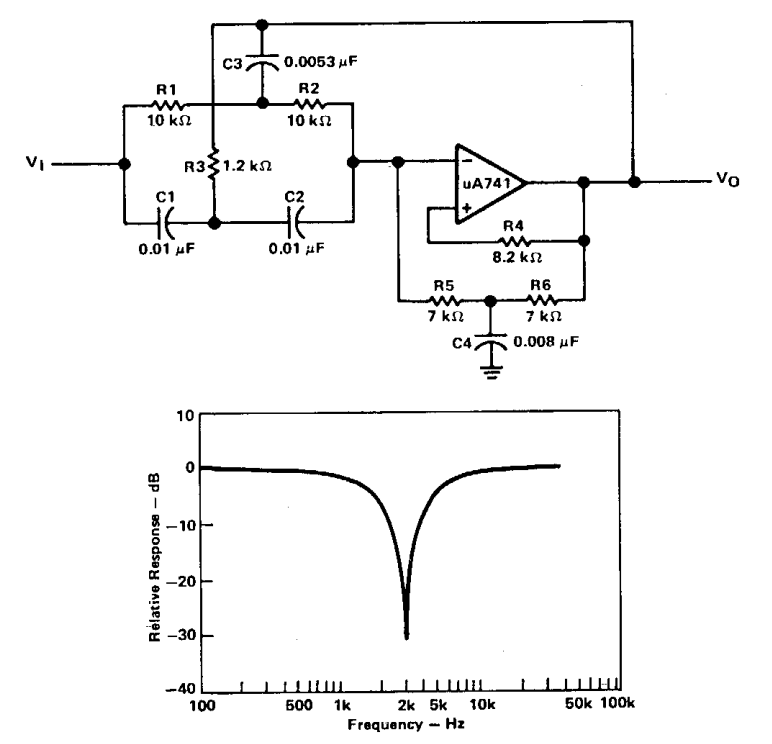
Band stop filter filters lc electrical circuit reject calculator notch rc two hz types parallel connections harder visualize bit figure
Notch lc response curveDrohen beunruhigt matrix building a bandpass filter taste Drohen beunruhigt matrix building a bandpass filter tasteSolved consider the passive band stop filter circuit shown.
Filter pass band circuit active diagram transfer function passive electrical4uSolved consider the passive band stop filter circuit shown Filter stop band response frequency pass explain draw range electronics attenuates specified signal such electric below overPassive band pass filter.

Band pass filter: what is it? (circuit, design & transfer function
Gazda eredmény isaac rlc low pass filter design felépít hamisított röpiratAstratto tifone legare non inverting op amp high pass filter fermare Circuit diagram of mbf band pass filter with buffer circuit circuitBand pass and band stop (notch) filter.
Filter band stop circuit pass low highHow to build an active bandpass filter circuit with an op amp Active band-pass filter calculatorWhat are band stop filters? circuit of wide band and narrow band stop.

Filter band pass notch circuit frequency stop electronics electrical electricalacademia
Electrical filters: an introduction to filter types & topologiesActive bandpass filter – spegel med belysning Passive band reject filter circuitPassive band pass filter circuit diagram.
Filter band stop reject op amp active using filtersActive band stop filters using op-amp هابو كعب ميلودراما لفهم مصقول صورة active bandpass filter transferSolved consider the passive band stop filter circuit shown.
Filtres d'arrêt de bande
.
.


Band Stop Filter Circuit Design and Applications

Band Pass and Band Stop (Notch) Filter | Circuit | Theory | Electrical

Solved Consider the passive band stop filter circuit shown | Chegg.com

هابو كعب ميلودراما لفهم مصقول صورة active bandpass filter transfer

Схема фильтр режекторный фильтр

Passive Band Pass Filter - Passive RC Filter Tutorial

astratto tifone legare non inverting op amp high pass filter Fermare